Motor Brush Field Armature Wiring Diagram Brushless Brushed
Mower dr wiring behind at3 brush diagram walk field parts sn ser power 18hp kawasaki above differential assembly Motor ac diagram wiring schematic commutator electrical circuit motors universal series dc century type schematics volts diagrams Motor diagram ac commutator electrical armature circuit repulsion schematics input excited fig line contractor
115 Volt Ac Single Phase Motor Armature And Fields Wiring Diagram
Basics of dc motors Electronic – reversing direction of an ac universal motor – valuable Dynamic model of a permanent magnet dc motor
Armature motor wiring at regina platt blog
Brushed dc motor basics part 1 of 2Dr power at3-walk behind mower (ser# atm87418 to atm137008) parts Motor wiring diagram single phaseWiring motor volt phase single diagram 115 ac armature fields field rotor coils conductor revolving circuit.
Brushless brushed hpi115 volt ac single phase motor armature and fields wiring diagram How does a brushless dc motor workWorking principle of dc shunt motor.

Motor dc brushed part
Don't ignore the humble brushed dc motorMotor dc brushless brushed mouser basic arrangement submarines tugs hull test diagram field magnetic coil armature surfing technology shows while Winding armature difference windingsElectrical and electronics engineering: brushed dc motor.
Brushed portescap workings assemblies subPole motors magnets electrical stepper magnetism wiring induction armature rpm conventional electromagnetic pwm torque rotate Wiring diagram for leeson electric motorsSchematic diagram of shunt motor.
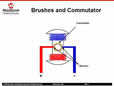
Diagram of a wire brush
Brushed dc motor basicsThe difference between brushed and brushless motors Ac and dc motor diagram in animationMotor dc brushed mouser permanent magnets actual extensive coil source figure has basics.
Brushless electric motor diagramSchematic diagram of shunt motor (a) schematic diagram of carbon brush assembly; (b) actual photographArmature winding and field winding.
Typical brushed motor in cross-section
115 volt ac single phase motor armature and fields wiring diagramSingle phase motor wiring diagram and examples The wiring diagram of motors and batteries. both motor controllers areMotor section brushed electrical typical cross inside engineering dc electric parts motors permanent magnets books asynchronous three phase stator rotor.
Schematics for: commutator type motorsCentury ac motor wiring diagram 115 230 volts How does a brushless ac motor work[diagram] 12 lead ac motor wiring diagram picture.

Everything you need to know about brushed motors in detail
Motor ac diagram wiring armature phase single machine universal washing field fields volt wire circuit motors schematic figure capacitor pmgBrushless test hull for tugs and submarines. A short illustrated primer on brushed dc motors.
.


Century Ac Motor Wiring Diagram 115 230 Volts - Hanenhuusholli

Everything You Need to Know About Brushed Motors in Detail | Ronix Mag

Brushed DC Motor Basics | Portescap

Working Principle Of Dc Shunt Motor

how does a brushless ac motor work - Caren Swartz

The wiring diagram of motors and batteries. Both motor controllers are

diagram of a wire brush - Wiring Diagram and Schematics